carr3r

Arduino Smart Window Sticker for vehicles - Part 3

Well, this is very embarrassing to assume but, after doing some math, I realized my first approach of storing all symbols and transitions into a big array it's just a huge, massive absurd.

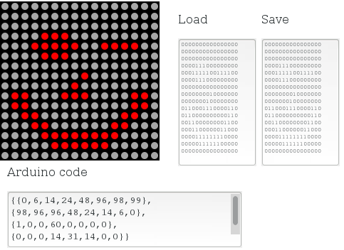
Each symbol, like "A" or "a" uses 32 bytes (16x16 LEDs) of storage memory. Therefore, just to store the whole alphabet and all digits, it would take (26 letters lowercase + 26 letters uppercase + 10 digits) 62 * 32 bytes, that equals 1984 bytes. So far, so good, since Arduino has ( 32kb - 5kb that is used by the bootloader) approximately 27Kb of storage memory available to our code. The problem is that each symbol transition (lets say, to scroll a character to one side) takes 16 frames to happen. In other words, to slide a symbol "A" to the left, bringing a "B" symbol from the right, takes (16x32) 480 bytes of storage. Now the absurd: if we have 62 symbols and considering that all transitions happen towards one single side (which isn't our case since it would be nice to have the text scrolling up/down/left/right), they can transit on 62² different possible combinations. That would take, at least, (3844*480bytes) 1801Kb of storage, more than sixty! times the available storage space. So, in short, storing transitions was never a feasible option, I just hadn't realized it yet.

To fix that, I embedded all the necessary functions to make symbol transitions into the Arduino. As I said before, it compromises the speed that the Arduino can paint/refresh each frame (since it requires quite a lot of bit "polishing") but the outcome was still acceptable.

I also included a buzzer to the circuit, so I can feedback the commands sent through the remote control, specially when I'm not looking at the board. I dit not use Arduino's Tone library since it collides with the IR receiver's library (both use the same timer interrupt). Instead, I used PWM over the analogWrite function to control the buzzer.

I also used a very handy library for storing/retrieving information on the Flash memory available at http://arduiniana.org/libraries/flash/ .

Now I'm working on building a plastic case for holding the whole circuit. Planning on doing it with a 3D printer.
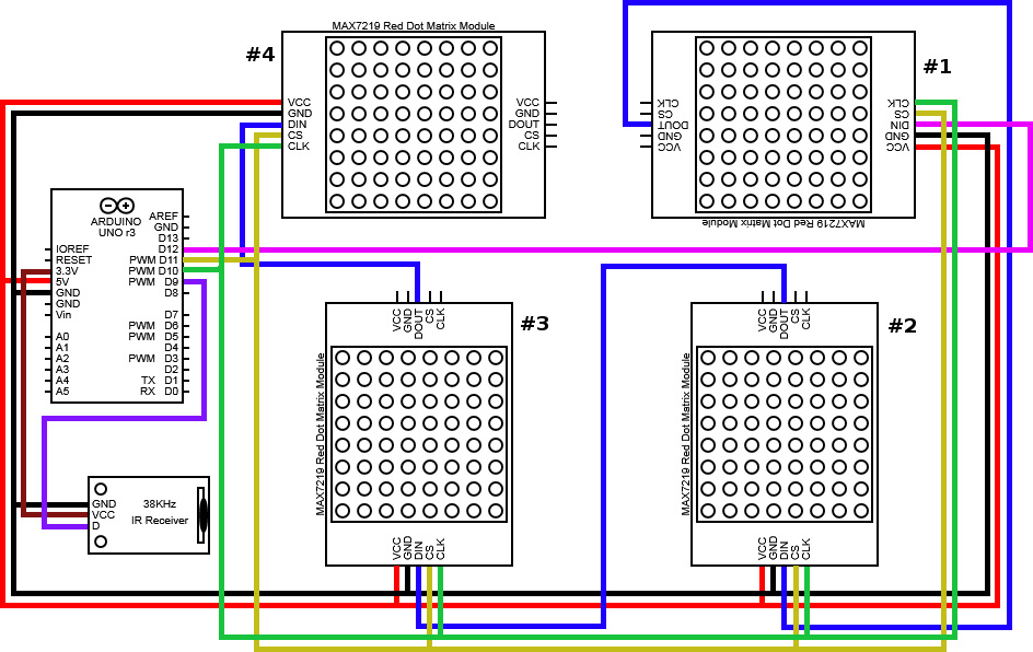
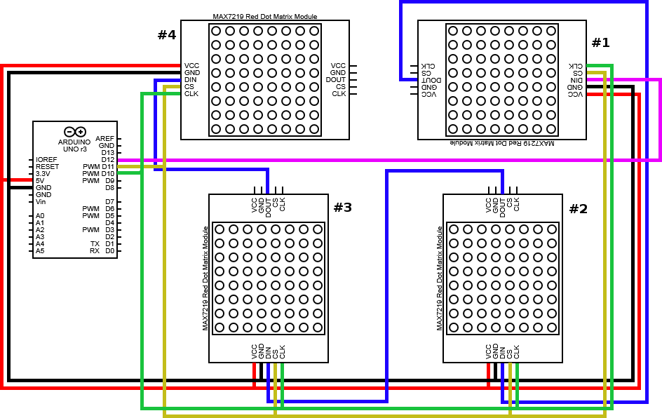
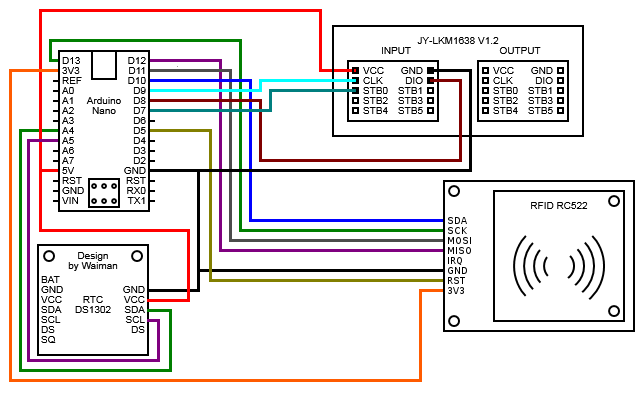
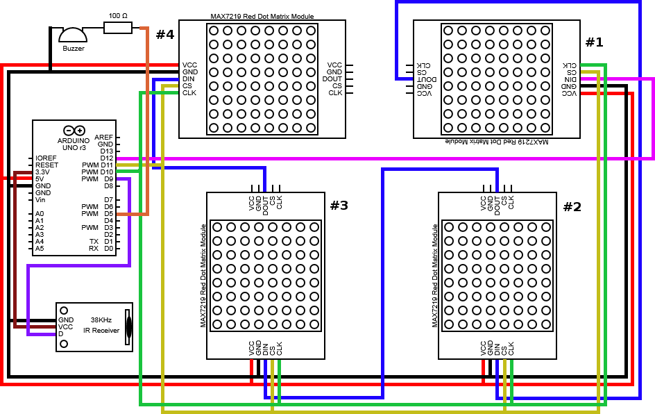
New wiring diagram:

 undefined

Necessary library for handling stuff on the Flash memory: Flash.zip

Source code

Arduino Smart Window Sticker for vehicles - Part 2

After spending more time with my adapted 16x16 LED board (made with four 8x8 red dot LED matrices - as shown in Part 1), I added an IR receiver module to the circuit and used an "old" 3.7v lithium battery (taken from a broken Motorola Defy smartphone) to power it.

A long time ago I bought an IR Kit for Arduino from DFRobot and it came with an useful IR remote control. Using the sample source code and wiring diagram available at the DFRobot's wiki, I managed to identify the frequencies related to all buttons from the remote control.

To be able to use the lithium battery to power Arduino, I took an USB female plug from an old USB hub and, following the USB Pinout description available here, I simply connected the VCC and GROUND pins to the + and - battery pins, respectively, as illustrated at the picture below.

undefined

The IR receiver module specifies 5V for power supply. As I was planning on using 3.7V for powering Arduino, I didn't bother to connect the IR receiver's VCC pin at Arduino's 3V3 pin, and give it less power than I was "required" to. And guess what, it worked like a charm!

New wiring diagram:0

undefined

Necessary library for the IR module: IRremote.zip

Source code


Arduino Smart Window Sticker for vehicles - Part 1

You're driving around aimlessly when you suddenly notice that, in the car just behind you, there is a beautiful and cheerful girl, singing by herself. Wouldn't it be nice to communicate with her, to throw away an innocent compliment and "attract" her attention? Or maybe you really need to notify something on the road, call names, make fun or even advertising something: your company, a trademark, your candidate, whatever. This project is about creating a smart sticker that would enable all these sort of things to happen.

With four 8x8 red LED dot matrix boards, like the ones available in DX, I was able to buld a 16x16 matrix board, sizing approximately 6.5x6.5 centimetres. It's little, but yet very visible. The downside of my final board is that each one of the tiny 8x8 matrix boards ended up in one different position, implying on several calculations to translate a 16x16 matrix into 4 8x8 rotated matrix at once.

After spending some time toying around with the source code, I realized that it would be very difficult to rely on the Arduino to make all calculations/translations in runtime and yet display the information within an acceptable time. So I decided to create a drawing board, with HTML& Javascript, to help me out with the drawing issue, and coded all the necessary math in PHP for translating the 16x16 matrix into 4 8x8 matrices.

undefined

This board can be seen in http://www.carr3r.com.br/matrix . I also coded a PHP script that calculates all the frames necessary to fade in and fade out an image, so all the Arduino was to do is to read an array of matrices and display each element of it (actually it slides a frame towards left, right, up and down - http://www.carr3r.com.br/matrix/transition.html).

The video below shows the current state-of-art of this project.

Next steps:

  • Create several animations;
  • Install an infra red sensor, so I can control what the board displays with an ordinary infra red remote control.


Updated on March 24, 2014

Material list:

Circuit Diagram (made with Circuit Diagram and GIMP):

undefined


Necessary library: LedControl.zip (documentation)

Source code: _16x16RedDotMatrix.ino

NFC Stopwatch Counter for exercises in swimming pool - Part 1

Swimming is one of my favorite sports, especially in open waters. But, to be able to swim in the sea, one must train in the swimming pool. The relationship between time and distance is the key to measure how bad/good we are doing, and it's something import to note whenever we follow a training plan. Therefore, time tracking will allow us to notice any improvement or regression. Having that said, this project is about automating time tracking over training sessions. Being able to send all lap times to the cloud should allow anyone to easily calculate training progressions.

In this first part of the project:

  • I managed to get my NFC reader board identifying NFC tags;
  • I adapted the key ring NFC tag into a finger ring NFC tag;
  • I learnt how to draw information over the LED board;
  • I got the RTC helping me out on counting time since it was difficult to me to keep the Arduino sharp on time while executing several instructions (as refining the information to be shown on the display, checking if there's any tag inside the antenna's reading field, etc);

My next goal is to install any wireless communication system on board. I first think of using Infrared sensors to transmit data to other nodes, mainly because its cheaper. The result can be seen in the video below. The circuit, component list and source code will be shortly available as soon as I get time to format these files. 

Updated on March 20, 2014

I am, now, decided to use a bluetooth module to collect data from these counters. Infra red communication systems are cheaper indeed, but not that much. Moreover, having a bluetooth module allows me to send data directly to my mobile phone, which is a big deal because I don't need another Arduino for interfacing the IR sensors.

Material list:

Circuit Diagram (made with Circuit Diagram and GIMP):

undefined


Necessary libraries:

Source code: SwimmingCounter.ino

Newer posts → Home